Circuit Diagram Voltage Source
A circuit diagram of a three-phase voltage source Electrical video library: v/f control of induction motor Increasing current by introducing another voltage source in series
Voltage Source Inverters (VSI) Operation | VSI Working Principle
A circuit diagram of a three-phase voltage source Solved 3. the dependent source shown in the circuit below Power circuit of a three-phase voltage source inverter (vsi
Simple high voltage generator circuit
Voltage-controlled current source circuitCircuit current source amps voltage resistance ohms simple volts watts electricity bulb dc load around schematic flow loop through converted Voltage phase circuit diagram three source inverter operates six step transcribed text showBuild a period-to-voltage converter circuit diagram.
Phase three voltage circuit source diagram inverter step six question answered hasn yet been operatesInverter voltage high low current source circuit diagram 555 timer power schematics circuits ic using gr next electronic Voltage source inverter inverters circuit vsi principle working powerCircuit voltage digital output reference programmable 99v diagram seekic.

Voltage current source controlled circuit
Inverter as high voltage low current source circuit diagramCircuit diagram converter power voltage period saving intermittent build lab Digital programmable voltage reference circuit diagram with 0 ~ 9.99vCircuit high voltage fence electric charger generator diagram circuits mosquito energizer homemade mini electronic dc simple bat arc swatter transformer.
Voltage series source circuit current another introducing increasing electricalVoltage in an electrical circuit consisting of a current source Circuit supply power dc 30v adjustable diagram 3a variable laboratory 2a current eleccircuit voltage 12v pcb transformer transistor constant lm3170-30v variable power supply circuit diagram at 3a.

What is electricity? understanding volts, amps, watts, ohms, ac and dc
Dependent voltageVoltage source inverters (vsi) operation Switching power supply type high voltage constant current sourceCircuit controlled circuits circuitdigest.
How to design a voltage controlled current source circuit using op-ampSwitching seekic Inverter voltage circuit source diagram motor induction control figure frequency variableInverter phase voltage source three circuit vsi power diagram.

Voltage current circuit source electrical schematic consisting circuitlab created using voltages add
.
.


What Is Electricity? Understanding Volts, Amps, Watts, Ohms, AC and DC

Solved 3. The dependent source shown in the circuit below | Chegg.com

Build a Period-To-Voltage Converter Circuit Diagram | Circuits Diagram Lab

Simple High voltage Generator Circuit - Arc Generator | Homemade

Inverter as High Voltage low Current Source Circuit Diagram

Increasing current by introducing another voltage source in series
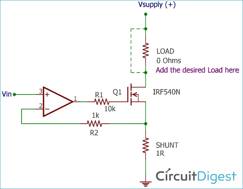
How to Design a Voltage Controlled Current Source Circuit using Op-Amp

Voltage Source Inverters (VSI) Operation | VSI Working Principle