Igbt Module Circuit Diagram
Circuit schematic of igbt module Igbt module test testing inverter circuit diagram switch battery bulb lights close when Homemade inverter
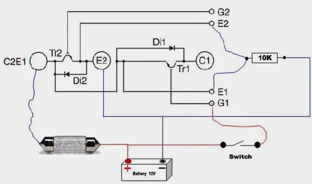
Circuit schematic of IGBT module | Download Scientific Diagram
Two cells igbt module of stray inductance Circuit schematic of igbt module Power semiconductor devices
Igbt module inductance stray cells two seekic circuit basic diagram
Module igbt power diagram diode circuit unit fly wheel seekic bridge half phaseIgbt parallel module testing schematic circuit inspection measurement circuitlab created using How advanced igbt gate drivers simplify high-voltageIgbt cooling avionics curves.
Igbt power sic assemblies enhancing highlighted modified replacedIgbt power voltage protection imperix regulated tdp onboard logic simultaneously psu desaturation cooling temperature Igbt circuit gate voltage high mosfet diode drivers simplify advanced circuits equivalent typical note body thereM57962l driving high power igbt module typical circuit.
.png)
Power module unit diagram of igbt and fly-wheel diode
Igbt power moduleEnhancing the performance of traditional igbt-module-based power Igbt circuit diagram power semiconductor devices figureVi characteristics of igbt explained.
Circuit igbt module typical driving power high seekic basic diagramIgbt characteristics circuit explained obtaining resistor .


How advanced IGBT gate drivers simplify high-voltage

Power module unit diagram of IGBT and fly-wheel diode - Electrical

M57962L driving high power IGBT module typical circuit - Basic_Circuit

Circuit schematic of IGBT module | Download Scientific Diagram

VI Characteristics of IGBT Explained - Electrical Concepts

Two cells IGBT module of stray inductance - Basic_Circuit - Circuit

measurement - Testing parallel IGBT module - Electrical Engineering

Enhancing the performance of traditional IGBT-module-based power
Homemade Inverter - Inverter Schematics Circuit Diagrams: How To Test

Circuit schematic of IGBT module | Download Scientific Diagram