Jk Ff Circuit Diagram
Solved: chapter 5 problem 10p solution Jk sequential flops Flip ff3 ff1 flops ff2 nand three gate solution
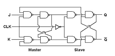
Digital Electronics and Logic Design: Master Slave JK FF
Input equation of sequential circuit using jk flip flop(हिन्दी ) Dff implement logic circuits Jk flip flop
Rgpv mca: master jk flip flop circuit diagram
Flip jk flop circuit sequential input equation usingSolved for the following circuit that uses two jk flip flops Jk flip flop verilog schematic ffCircuit jk circuitlab description.
Flip flop jk gate rs nand diagram circuit table symbol truth basic suffers two problems mainFf jk schematic using counter prevent reaching maximum beginning start after circuitlab created Flip flop jk diagram slave master explain block sequential basic working circuit logic sr nand symbol clock input does connectSolved: the three j-k flip-flops (ff1, ff2, ff3) and the nand gate.

T-ff to jk-ff
B): logic circuit diagram of memory element for jk-ff at 75%Jk tnx Jk circuitSlave flop nand logic flipflop flops circuitverse constructed.
Jk flop flip diagram circuit master rgpv mcaJk flip two circuit following active low clear timing diagram flops uses aa solved Implement a j-k ff using a dffDigital electronics and logic design: master slave jk ff.

Jk flip flop and the master-slave jk flip flop tutorial
Jk flip flops schematic simpler why use when circuit circuitlab created using flipflopWhat is jk flip flop? circuit diagram & truth table .
.

Solved: The three J-K flip-flops (FF1, FF2, FF3) and the NAND gate

flipflop - Why use JK flip flops when D flip flops are simpler
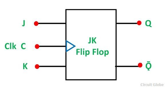
What is JK Flip Flop? Circuit Diagram & Truth Table - Circuit Globe

flipflop - Prevent JK-FF Counter to start from beginning after reaching

JK Flip Flop
RGPV MCA: Master JK flip flop circuit diagram

Solved: Chapter 5 Problem 10P Solution | Digital Design 6th Edition

Digital Electronics and Logic Design: Master Slave JK FF

T-FF to JK-FF | All About Circuits