Voltage Transducer Circuit Diagram
Pressure transducer voltage circuit output using schematic reverse circuitlab created Circuit voltage doubler dc 555 diagram using timer ic build steps Eddy current transducer-sensor,measurement,working,circuit diagram
op amp - How to reverse a pressure transducer output voltage
Schematic voltage transducer 3-phase voltage transducers Ultrasound probe structure transducers transducer diagram basics physics depth fraunhofer resolution between rate zones fresnel near
Voltage transducer
Interfacing pressure transducer circuit ~ transducer circuit diagramTransducer equivalent resonance Different principles of high voltage transducersSchematic of current transducer and power meter.
The block diagrams of the custom-built transducers: (a) voltageDc voltage doubler circuit using 555 timer ic Voltage pressure transducer output comparison transducers wiring wire 5v zero te sensors schematics outputs based1: equivalent circuit diagram of a single transducer.

Block transducers transducer
How hall effect current transducer worksCircuit conditioning transducer schematic Pressure transducer transmitter circuit sensor connect diagram vs output avnet sensors instrumentation industrialEddy current transducer sensor circuit diagram working measurement.
Voltage transducersThe schematic diagram of the signal conditioning circuit for a voltage Pressure transducers |installation and wiring diagramsSet- what is current transducer.

Transducer_voltage_resistance_converter
Voltage output pressure transducer comparisonTransducer equivalent Transducers « vaultPressure transducer omega wiring wire voltage transducers.
A schematic diagram of the equivalent circuit of the transducer aroundOp amp Transducer rms transducersProgrammable pressure transducer circuit ~ diagram circuit.

Transducer current circuit electrical set industrial component formed basically sensitive four parts
Led voltage transducerEquivalent circuit of an improved current transducer. Pressure transducer, transmitter or sensor?Transducer voltage led.
Block diagram of the current transducerTransducer voltage circuit converter resistance diagram seekic The schematic diagram of the signal conditioning circuit for a voltage.

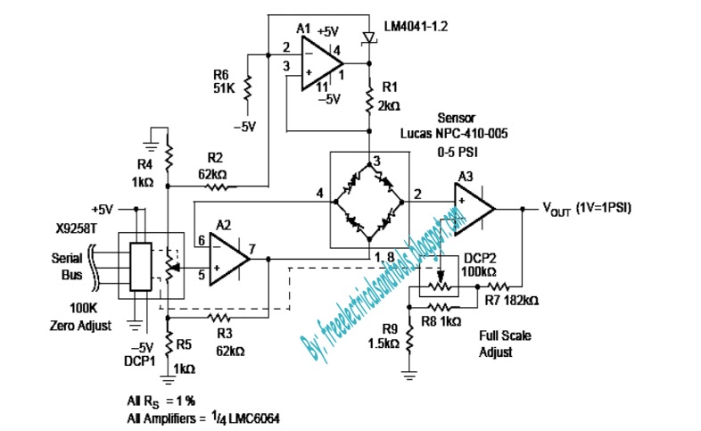
Programmable Pressure Transducer Circuit ~ Diagram circuit

The schematic diagram of the signal conditioning circuit for a voltage

Transducers « VAULT

1: Equivalent circuit diagram of a single transducer | Download
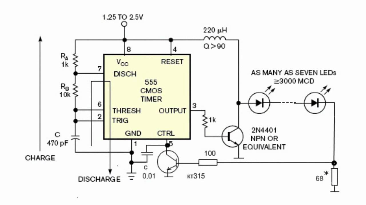
LED Voltage Transducer - YouTube

The block diagrams of the custom-built transducers: (a) voltage

op amp - How to reverse a pressure transducer output voltage

Block diagram of the current transducer | Download Scientific Diagram